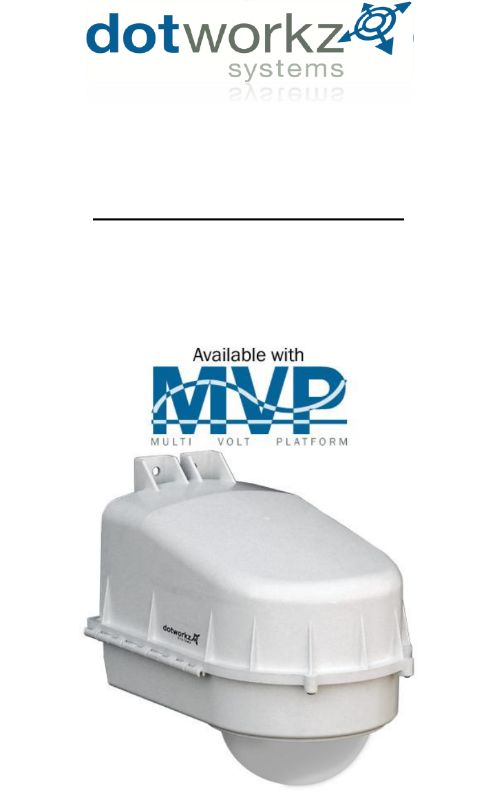
Dotworkz D3-TR-MVP Installationsanleitung
Stöbern Sie online oder laden Sie Installationsanleitung nach Überwachungskamera-Zubehör Dotworkz D3-TR-MVP herunter. Dotworkz D2-HB-MVP Benutzerhandbuch
- Seite / 33
- Inhaltsverzeichnis
- LESEZEICHEN
- PRODUCT INSTRUCTIONS 1
- Table of Contents 3
- LIMITED WARRANTY 4
- , INC. PRODUCTS 4
- PRODUCT INSTALLATION 5
- (RETAIN THIS DOCUMENT) 5
- 110 – 220 VAC 7
- 24 VAC/VDC 7
- Input Voltage to Enclosure 7
- Camera Power Setup 10
- (STANDARD 12VDC CONNECTOR) 10
- Installing Camera Bracket 14
- D2 Exploded Detail 32
- D2 Mounting Detail 33
Inhaltsverzeichnis
PRODUCT INSTRUCTIONS D2 SERIES ENCLOSURES
6 All D2 environmental enclosures come standard with a 12VDC Right Angle Barrel Plug (3.3mm x 5.5mm with a 1mm center pin) for majority of th
8 Stand Off Assembly Key for Camera Height Adjustment Camera mount stand offs can be adjusted to any height from 0” to 3.75” using assembly l
10 Installing Camera BracketAxis 214 PTZ1. Install the Axis 214 PTZ camera onto the D2 Camera Bracket with (3) m3-.5 screws, (3) m3 external lock w
12 Installing Camera BracketAxis 233D PTZ2. Do this by aligning the two holes on the D2 camera bracket with the Axis ceiling bracket adapter. Use
13 Installing Camera BracketAxis 233D PTZ6. Now slide the camera bracket with the camera into place to line up with 4 scr
14 Installing Camera BracketCanon VB-C3001. Install the Canon VB-C300 camera onto the D2 Camera Bracket center hole with (1) .25
15 Installing Camera BracketPanasonic NS-2021. Install the Panasonic NS-202 camera onto the D2 Camera Bracket center hole with (1) .25"-20 3/8
16 Installing Camera BracketPanasonic BB-HCM381/580/581 & KX-HMC2801. Install the Panasonic camera onto the D2 Camera Bracket center hole with
17 Installing Camera BracketSony RZ25N1. Install the Sony RZ25N camera onto the D2 Camera Bracket with (3) m3-.5 ½” Long screw (3) m3 External Lock
18 Installing Camera BracketSony RZ30N1. Install the Sony RZ30N camera onto the D2 Camera Bracket center hole with (1) .25"-20 3/8" Long
19 Installing Camera BracketSony RZ50N1. Install the Sony RZ50N camera onto the D2 Camera Bracket center hole with (1) .25"-20 3/8" Long
20 Installing Camera BracketSony RX550N1. Install the Sony RX550N camera onto the D2 Camera Bracket with (4) m3-.5 ½” long screws, (4) m3 external
21 Installing Camera BracketToshiba WB21A2. Do this by aligning the four holes on the D2 camera bracket with the Toshiba ceiling bracket adapter.
22 6. Now slide the camera bracket with the camera into place to line up with 4 screws from the standoffs.Continued . . . . . . . .Installing Came
23
24
25 Optional Steady Step Mounting System Steady Step Bracket Steps adjust in ¼” increments. To adjust 1/8” between step settings, add 1/8” brass m
Table of Contents Limited Warranty Info ..………………………………………………………………………………………………………………………………………………………………………………... 0 Product Installation Precautions
26
27
28 D2 Exploded Detail
29 D2 Mounting Detail
0 LIMITED WARRANTY DOTWORKZ, INC. PRODUCTS DOTWORKZ SYSTEMS INC. Warrants this Product to be free from defects in material or workmanship, a
1 PRODUCT INSTALLATION PRECAUTIONS – WARNINGS – ADDITIONAL INFORMATION (RETAIN THIS DOCUMENT) IMPORTANT SAFEGUARDS 1 Read Instructions - Al
2
3 Site Power Available110 – 220 VAC Power Source – Single Phase Only24 VAC/VDCStep Down TransformerHigh Voltage to 24 VACSite Power AvailableMVP Vo
© 2020, manymanuals.de. Alle Rechte vorbehalten. | 0.564 s |
 Manymanuals.com
 Manymanuals.de
 Manymanuals.fr
 Manymanuals.it
 Manymanuals.pl
 Manymanuals.cz
 Manymanuals.es
 Manymanuals-pt.com
Kommentare zu diesen Handbüchern